
2D Encoder
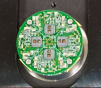
An encoder with four optical reflective encoders on a single board that reads the pattern of an XY two-dimensional scale directly. Measurement accuracy is determined by the scale itself and is not affected by stage errors such as pitching, yawing and rolling. Because the orthogonality of the X and Y axes is also referenced to the scale master, it can also be used in inspection equipment and similar applications.
Features
- Accuracy is set by the scale, unaffected by stage guide errors
- Four encoders on one board detect X and Y simultaneously
- X/Y orthogonality is also referenced to the scale master
- Four scale types in Ni and synthetic quartz
- Multiplication range 1 to 512
Measurement Principle
The encoder board is placed facing upward in the hollow center of the XY stage and reads, from below, the pattern of the scale plate that moves together with the stage. The four encoders are arranged rotationally symmetrically, and their center is the measurement center of the 2D encoder. Because the scale pattern moves together with the stage even if the stage guide does not travel perfectly straight, errors originating from the stage do not enter the measured values. By aligning the measurement center with the point to be measured, such as the center of a microscope's crosshair reticle, the XY coordinates of that point are obtained directly. Errors in the scale pattern itself can be handled by calibrating it with a traceable measuring instrument.
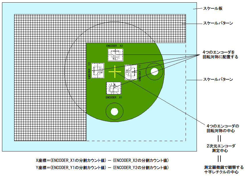
Arrangement of the four encoders and the measurement center
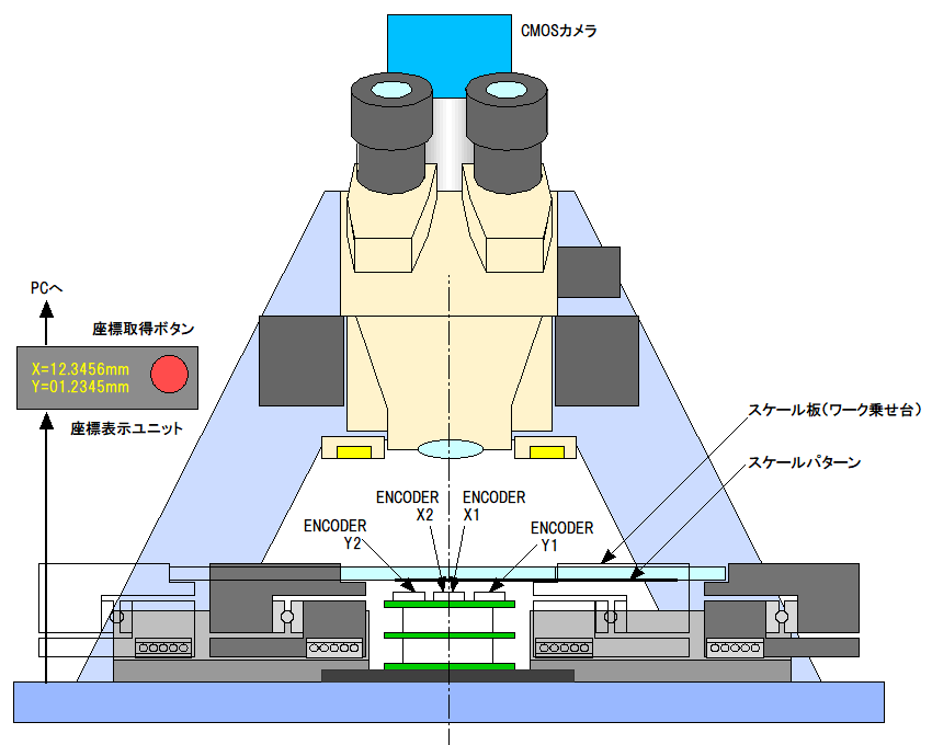
Example built into a measuring microscope (cross section)
Encoder Specifications
The standard scales do not support the Z phase. The FFC and FFC connector are optional.
| Item | Specification |
|---|---|
| Detection method | Optical reflective |
| Encoders | 4 (2 each for X and Y) |
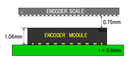
| Board size | φ36.5 mm, 0.6 mm thick |
| Gap to scale | 0.75±0.25mm |
| X/Y resolution | 64μm |
| Multiplication range | 1~512 |
| Output signal | TTL (A+,B+,A-,B-) |
| Output connector | Surface-mount for FFC, 18 pins, 0.5 mm pitch |
| Power supply | 5V, 500mA |
| Environmental resistance (temperature) | -10~85℃ |
| Environmental resistance (humidity) | 10–85% (non-condensing) |
Scales
Adhesive tape and spray adhesive are not included.
| Model | Pattern (X×Y mm) | Material | Thickness (mm) | Dimensions (X×Y mm) | Mounting |
|---|---|---|---|---|---|
| S106X85Y64M | 106×85 | Ni steel | 0.15 | 112×92 | Adhesive tape |
| S133X95Y64M | 133×95 | Ni steel | 0.15 | 139×101 | Adhesive tape |
| S350X350Y64M | 350×350 | Ni steel | 0.15 | 360×360 | Spray adhesive |
| S212X212Y64Qz | 212×212 | Synthetic quartz | 5 | 229×229 | Dropped into a frame |
Connector Pin Assignment
FFC, 18 pins, 0.5 mm pitch
| Pin | Signal | Pin | Signal |
|---|---|---|---|
| 1 | +5V | 10 | I- |
| 2 | +5V | 11 | I+ |
| 3 | GND | 12 | B- |
| 4 | GND | 13 | B+ |
| 5 | SEL3 | 14 | GND |
| 6 | SEL2 | 15 | +5V |
| 7 | SEL1 | 16 | GND |
| 8 | Index SEL | 17 | A- |
| 9 | CAL | 18 | A+ |
Options
| Item | Specification |
|---|---|
| FFC | 18 pins, 0.5 mm pitch, 200 mm or 300 mm long, 9.5 mm wide |
| FFC breakout board | 18 pins, 0.5 mm pitch |
| FFC connector | 18 pins, 0.5 mm pitch |
Application: Distortion Measuring Microscope
As a system built around the 2D encoder, we also offer a distortion measuring microscope. In processing machines that use galvanometer scanners, such as laser markers, the drawn pattern is distorted by the aberration of the focusing lens and the angular errors of the two galvanometer scanners (distortion). Because the distortion also changes with the optical adjustment of the laser, correction data must be created for each machine every time it is installed. A measuring microscope equipped with the 2D encoder acquires XY coordinates simply by aligning each intersection of the drawn grid pattern with the crosshair reticle, and outputs them to a CSV file. Applying these coordinates to the galvanometer scanner's correction software to create correction data makes a drawing accuracy of about 1 μm achievable. Because it can be built with a compact, lightweight XY stage, it can be taken to the site where the processing machine is installed.
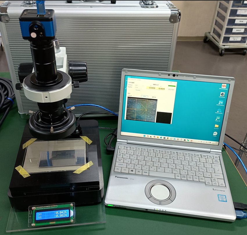
Manual stage model 9060
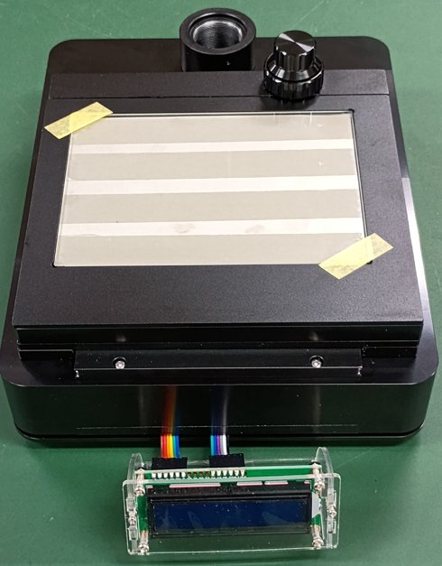
XY stage of the 9060 (2D scale and LCD display)
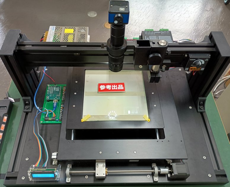
Motorized stage model 190190
Measuring Microscope Specifications
| Item | Manual stage model 9060 | Motorized stage model 190190 |
|---|---|---|
| Measuring area | 90×60mm | 190×190mm |
| Measuring resolution | 0.1μm | 0.1μm |
| Scale | S133X95Y64M | S212X212Y64Qz |
| Coordinate output | USB (saved as a CSV file by the PC software) | USB (saved as a CSV file by the PC software) |
Distortion Correction Workflow
Drawing, measurement and correction are repeated until the measured values fall within the tolerances.
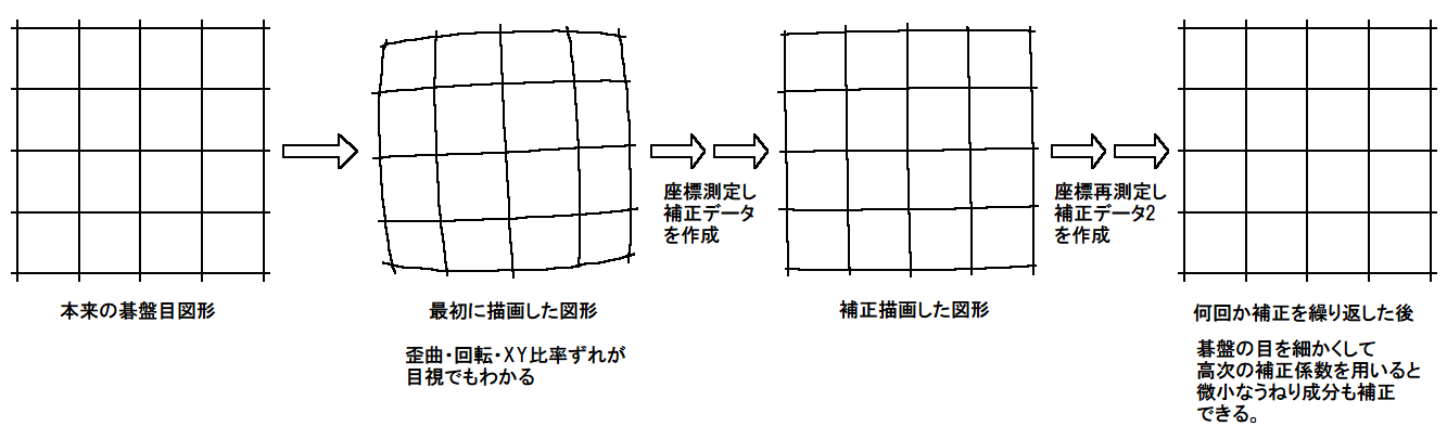
Example of grid pattern correction
| STEP | Description |
|---|---|
| 1 | Draw a grid pattern with the processing machine |
| 2 | Acquire the XY coordinates of each intersection in turn with the measuring microscope and save them to a CSV file |
| 3 | From the measured values, calculate the magnification error, distortion and coordinate-axis errors (galvo X axis vs. Y axis, galvo axes vs. stage axes) and compare them with the tolerances. If a tolerance is exceeded, create correction data and return to STEP 1 |
| 4 | Apply the correction data and perform laser processing |
Measurement Software
Aligning an intersection with the crosshair reticle and pressing the coordinate acquisition button saves the XY coordinates and the microscope camera image. A guidance screen leads you through acquiring the grid coordinates in order, and the acquired coordinates are output to a CSV file together with the ideal values.
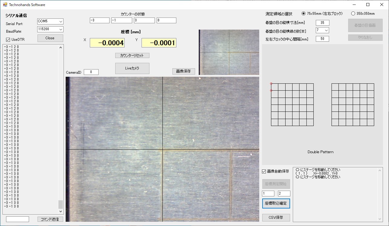
Coordinate acquisition software screen
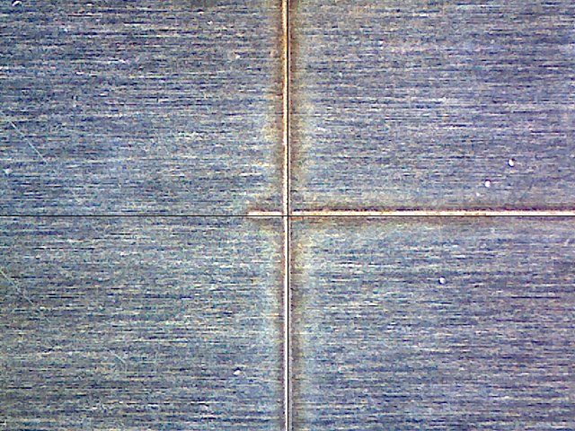
Microscope image saved when coordinates are acquired
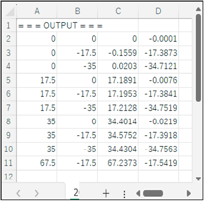
Example of CSV output (ideal and measured values)